 |
| Designation |
Signal |
Description |
1.Mounting
hole |
TN16
|
16m/m series |
| 2.Type |
|
| knob operator |
| key operator |
|
| 3.Shape |
|
|
| 4.Operator Protection |
|
|
| 5.Color |
|
|
| 6.Positions |
1
|
 |
90° 2-position |
|
2 |
 |
90° 2-position spring return from
right |
|
3 |
 |
180° 3-position |
|
4 |
 |
150° 3-position spring return
from right |
|
5 |
 |
150° 3-position spring return
from left |
|
6 |
 |
150° 3-position 2-way spring return
|
|
7 |
 |
90° 3-position |
|
8 |
 |
90° 3-position spring return form
right |
|
9 |
 |
90° 3-position spring return from
left |
|
0 |
 |
90° 3-position 2-way spring return
|
|
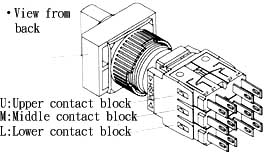
7.Type of contact blocks
fitted |
|
2-positon |
3-position |
|
— |
1a1b 0 1a1b |
1a1b 1a1b 1a1b |
|
| 8.Key withdrawable |
1 |
|
0,1 |
2 |
0key withdrawable |
3 |
1key wintdrawable |
4 |
|
0,1,2key wintdrawable |
5 |
0 key wintdrawable |
| 9.Key No. |
A |
F |
2132 |
3123 |
B |
G |
2231 |
3133 |
C |
H |
2313 |
3213 |
D |
I |
2331 |
3231 |
E |
J |
3131 |
3331 |
| 10.Terminal |
|
|
|
| ˇˇKSR/KSS/KSL Types only available in black colors.
|
| ˇ¤Characteristics |
| Contact resistance |
50m¦¸ max. (initial) |
| Insulation resistance
|
100M¦¸min.(at 500VDC) |
Dielectric strength |
1000VAC,50/60 Hz for 1 minute between non-continuous
terminals
2000VAC, 50/60 Hz for 1 minute current-carrying
part and ground |
Vibration |
Mechanical durability:
10 to 55 Hz 1.5mm double amplitude |
Shock |
Mechanical durability:
Approx. 500m/sec2 (approx. 50G's)
Malfunction durability:
Approx. 500m/sec2 (approx. 50G's) |
Ambient operating temperature |
Operating: -25ˇć to 55ˇć
Storage: -30ˇć to 80ˇć |
Humidity |
45% to 80% RH |
Mechanical Life (min) |
250,000 operations |
Electrical Life (min) |
100,000 operations |
|
|
ˇ¤Key withhdrwable |
| 2-positions |
3-positions |
 |
 |
|
ˇˇ2-positions
|
Key withhdrwable |
1 |
2 |
3 |
| Positions |
0 |
1 |
0 |
1 |
0 |
1 |
1 |
|
|
|
2 |
|
|
|
|
ˇˇ3-positions
| Key withhdrwable |
1 |
2 |
| Positions |
1 |
0 |
2 |
1 |
0 |
2 |
3 |
|
|
4 |
|
|
5 |
|
|
6 |
|
|
7 |
|
|
8 |
|
|
9 |
|
|
0 |
|
|
•:Key withhdrwable |

| ˇ¤The operating angle range can be changed
as shown below by setting the attached flange
by45° in combination with the contact
block.In this case,the minimum mounting pitch
is 26mm because the contact block is shifed
by 45 °from the flange. |
 |
|
ˇ¤Contact arrangement
and operator positions:2-position selector switch/key
switch
| Contact arrange-ment |
|
|
|
op
er
to
r
po
si
ti
on
|
 |
 |
 |
 |
 |
 |
 |
 |
3-position selector switch/key switch
| Contact arrange-ment |
|
|
op
er
to
r
po
si
ti
on |
 |
 |
 |
 |
 |
 |
 |
 |
 |
|
|
|
| |

