| .Fastening of the switch cable |
| ����The switch bodies are filled with resin for sealing purposes.To acoid stressing |
| ��the cable and switch body,fasten the switch at 5 cm or farther away from the |
| ��switch body,should the wire be bent,the bending radius shall be at least 45mm. |
|
|
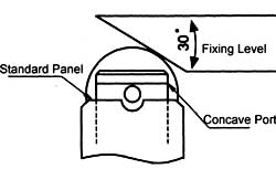
| .Installation |
| ����The service life and accuracy of switches will be effected by the shape of actua- |
| ��tor operation frequency&over travel.So the angular of the fixing level should be |
| ��about 30��,the surface finish of the
fixing level should be over ������ ,the hardness |
| ��is from HV400~500.When installing,the position of the concave part should be |
| ��above the standard panel |
|
| |
��������.Contacttypes |
|
 |
|
| |
| .Switch bank mounting |
| ����A maximum of six switches may be mounted together as a switch bank.During |
| ��the installation,the convex part of the switch back.The mounting panel shall be |
| ��6mm or thicker. |
|
| |
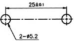
| .Mounting holes |
| ��Mount the switch body to a rigid |
| mounting panel using two M5 |
screws.
|
 |
|
| .Mounting |
| ��Reccmmended tightening torque according to the follwing form. |
Model |
Screw type |
Torque |
1 |
M5 fastening screws |
43.4~52lb.in
(50~60kgf.cm) |
2 |
M3.5 installing screws |
6.9~7.9lb.in
(8~9kgf.cm)
|
|
|
| |